Prepare the surface area where the sensor is to be mounted. Grind down any raised lettering or imperfections on the surface of the casting.
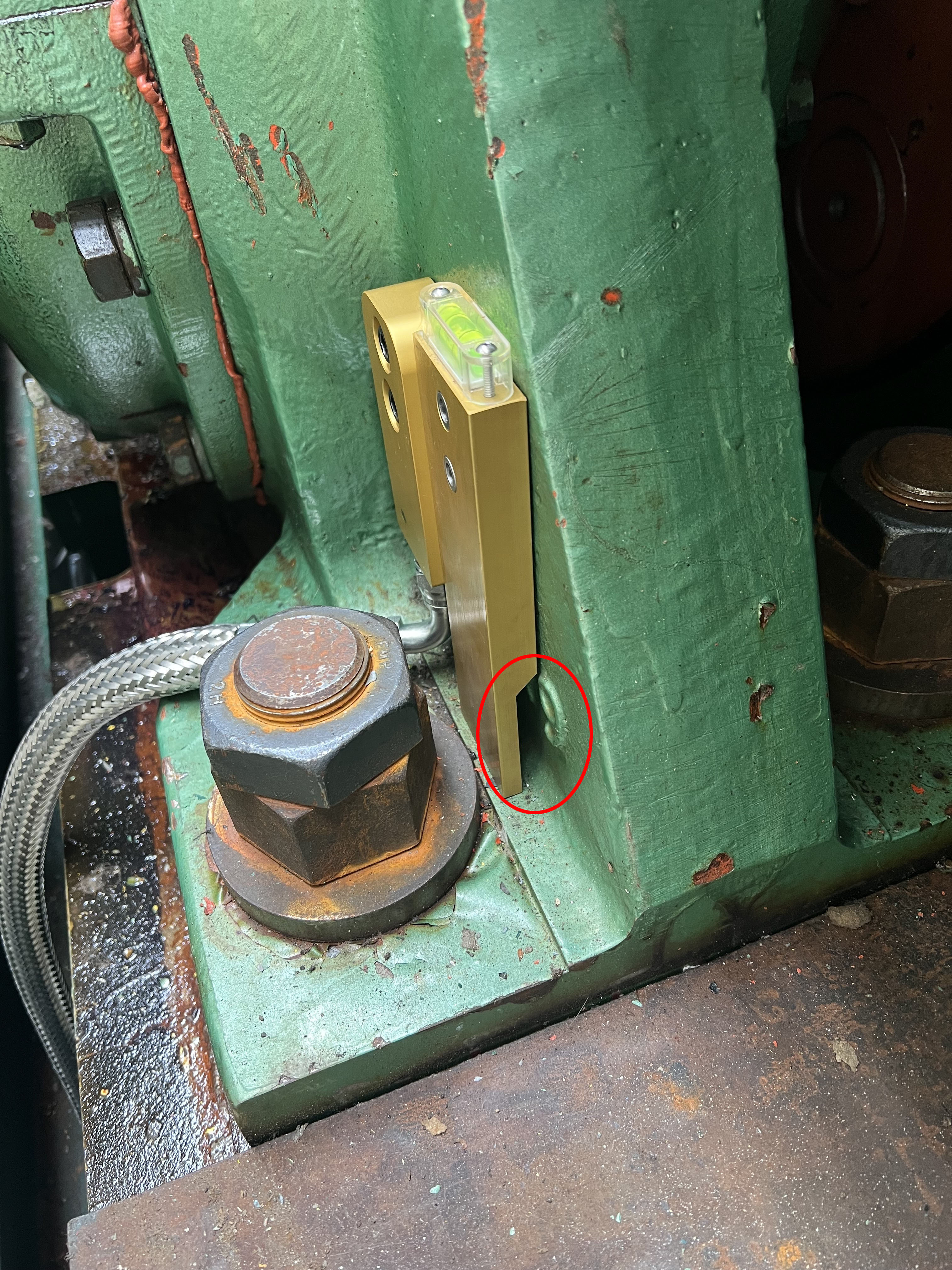
Firmly clamp the mill sensor template in the location that the sensor will be mounted. Make sure that it fully seats flat on the surface of the gusset.
Make sure that the mill sensor template rests on the base of the bearing housing.
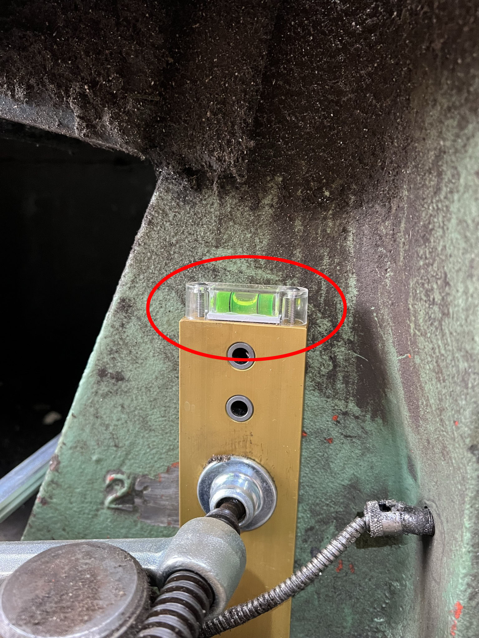
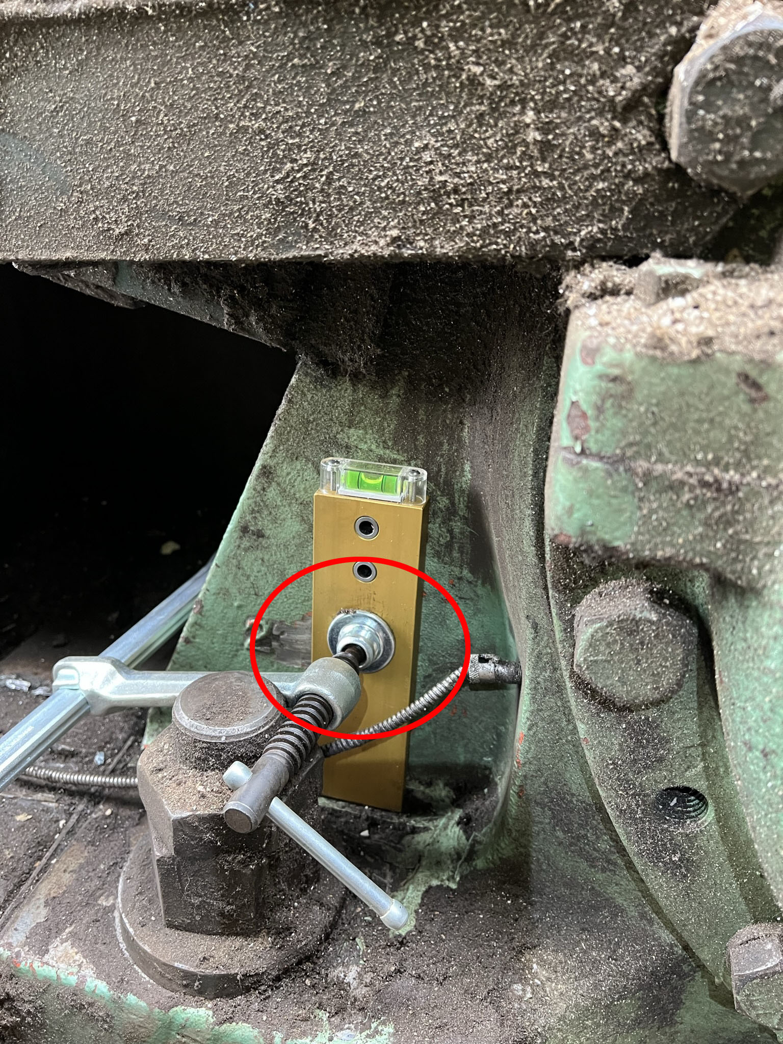
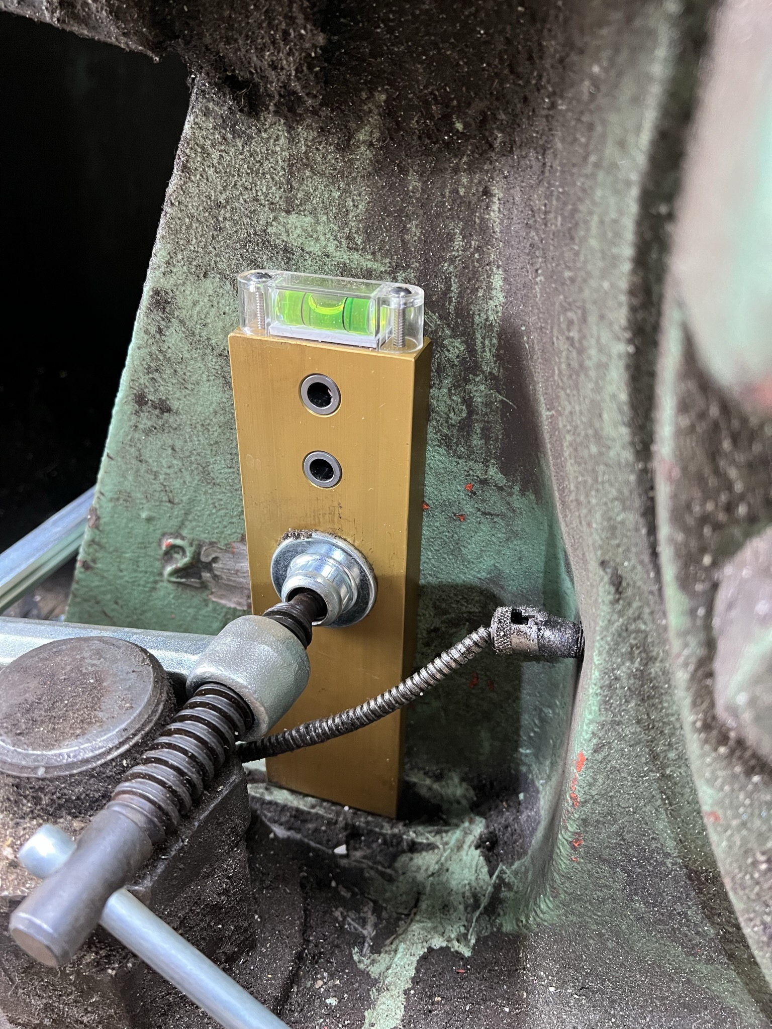
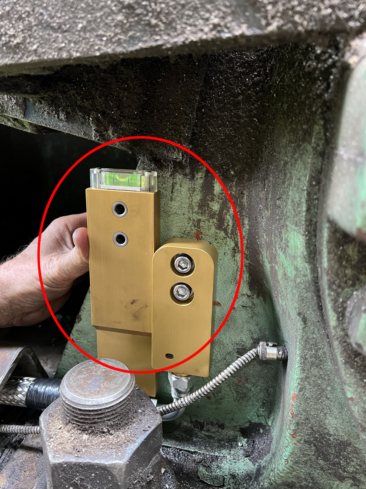
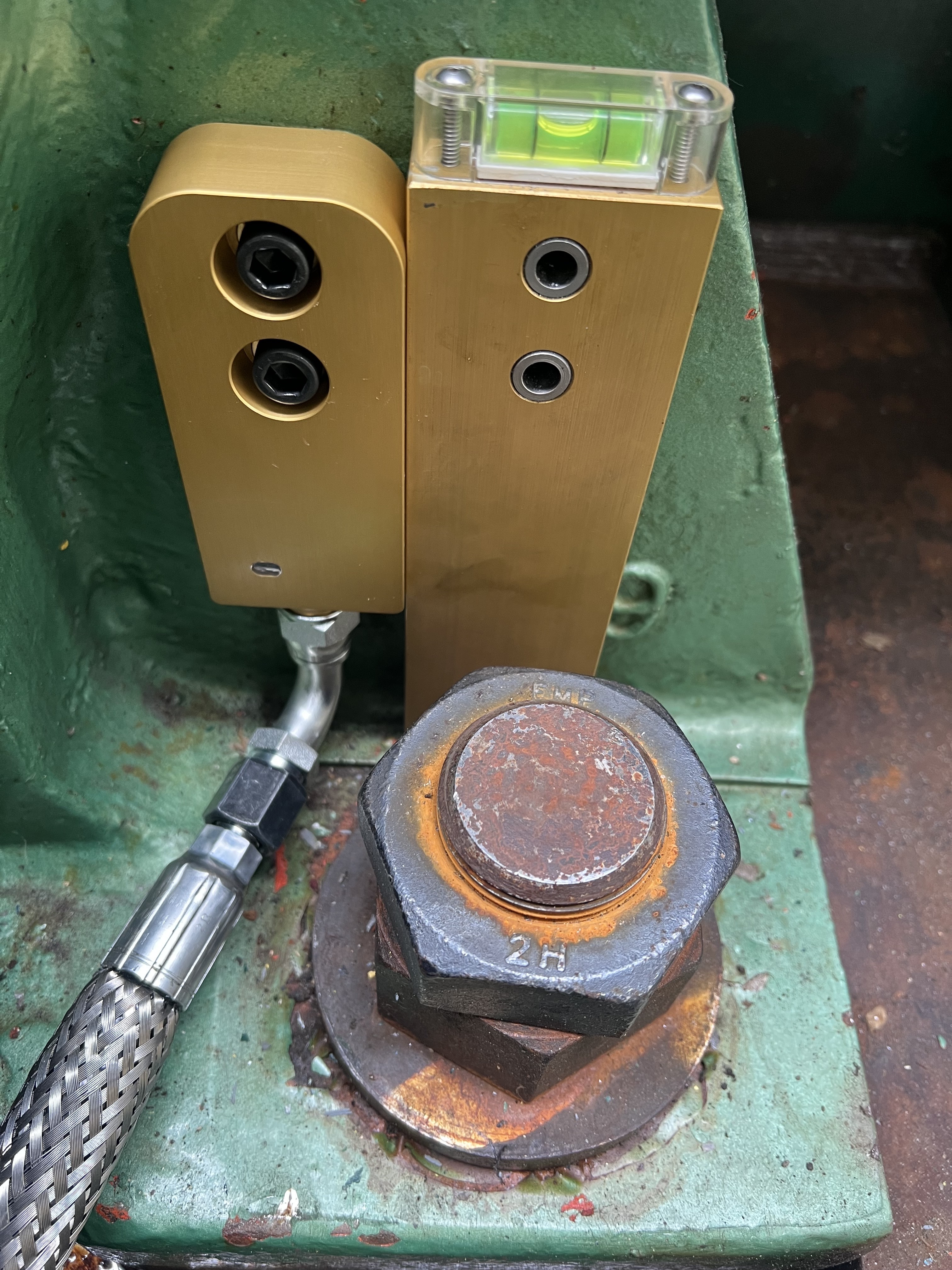
Make sure that the template is mounted true to perpendicular. Use the level on the top of the template to confirm accuracy.
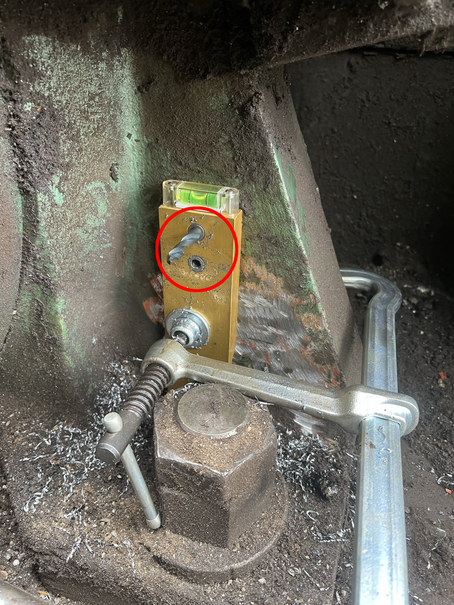
Drill the top hole first. Minimum drill depth is 1 inch. Once this hole has been drilled, clean the hole using lubricant and insert the stubby 5/16 inch drill backwards into the hole to "key" the template and prevent it from moving while you drill the lower hole.
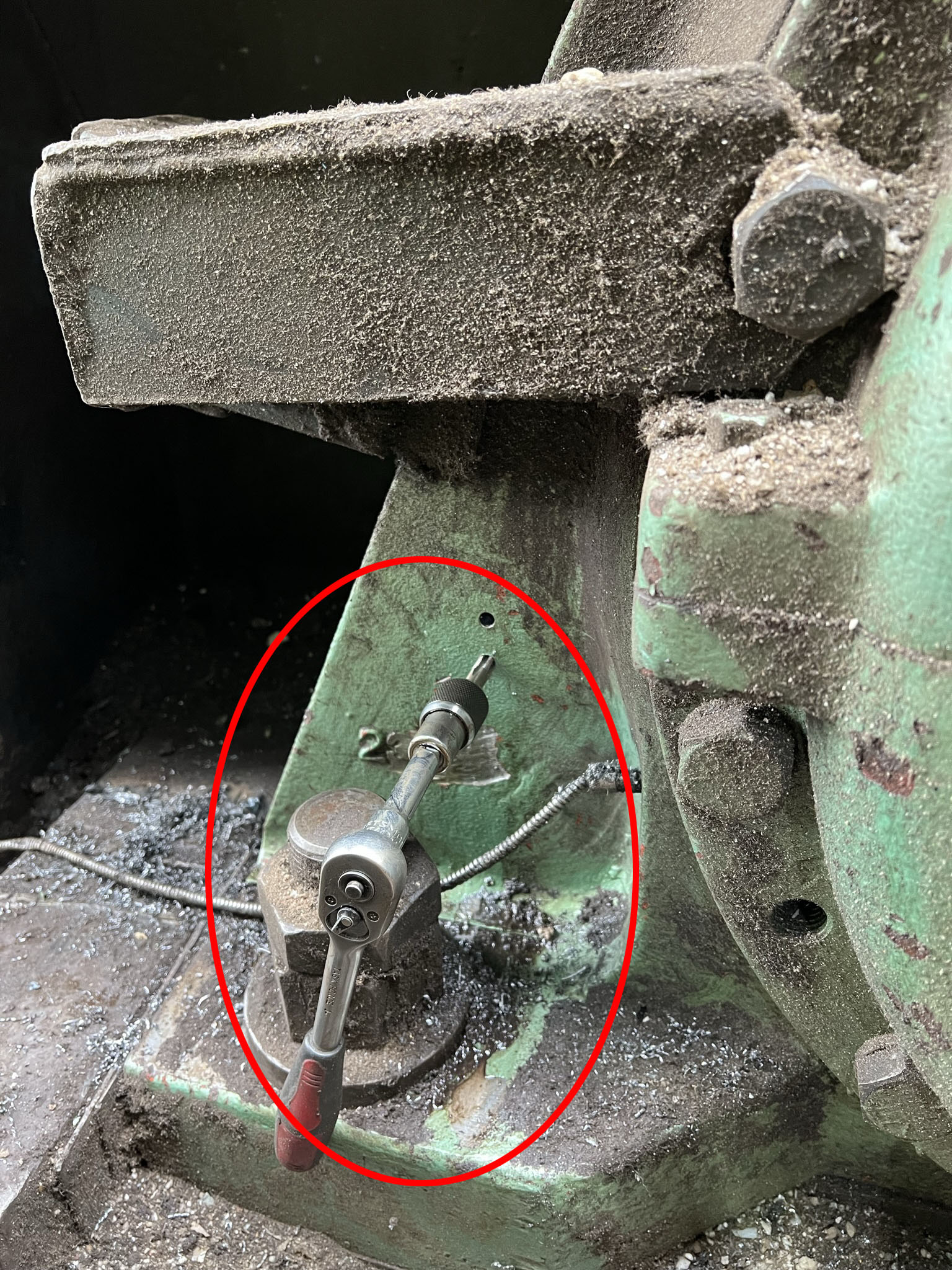
Use the drill bits and threaded taps provided to drill and tap the sensor bolt holes. Minimum drill depth is 1 inch. Regularly clean out the holes during the drilling and tapping process to ensure that excess metal swarf is removed. Use the tapping fluid provided to lubricate the cutting surfaces.
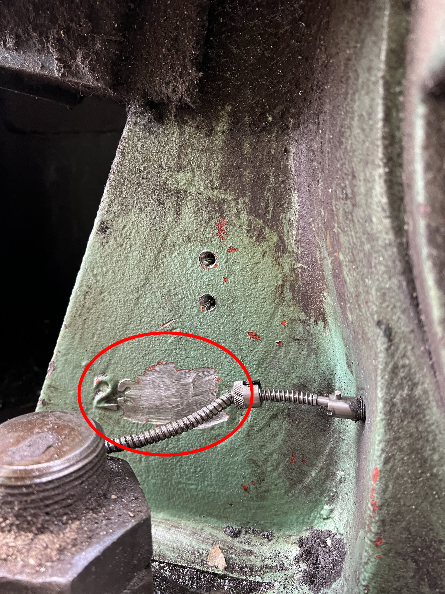
Here is an example of a well prepared surface ready for sensor mounting.
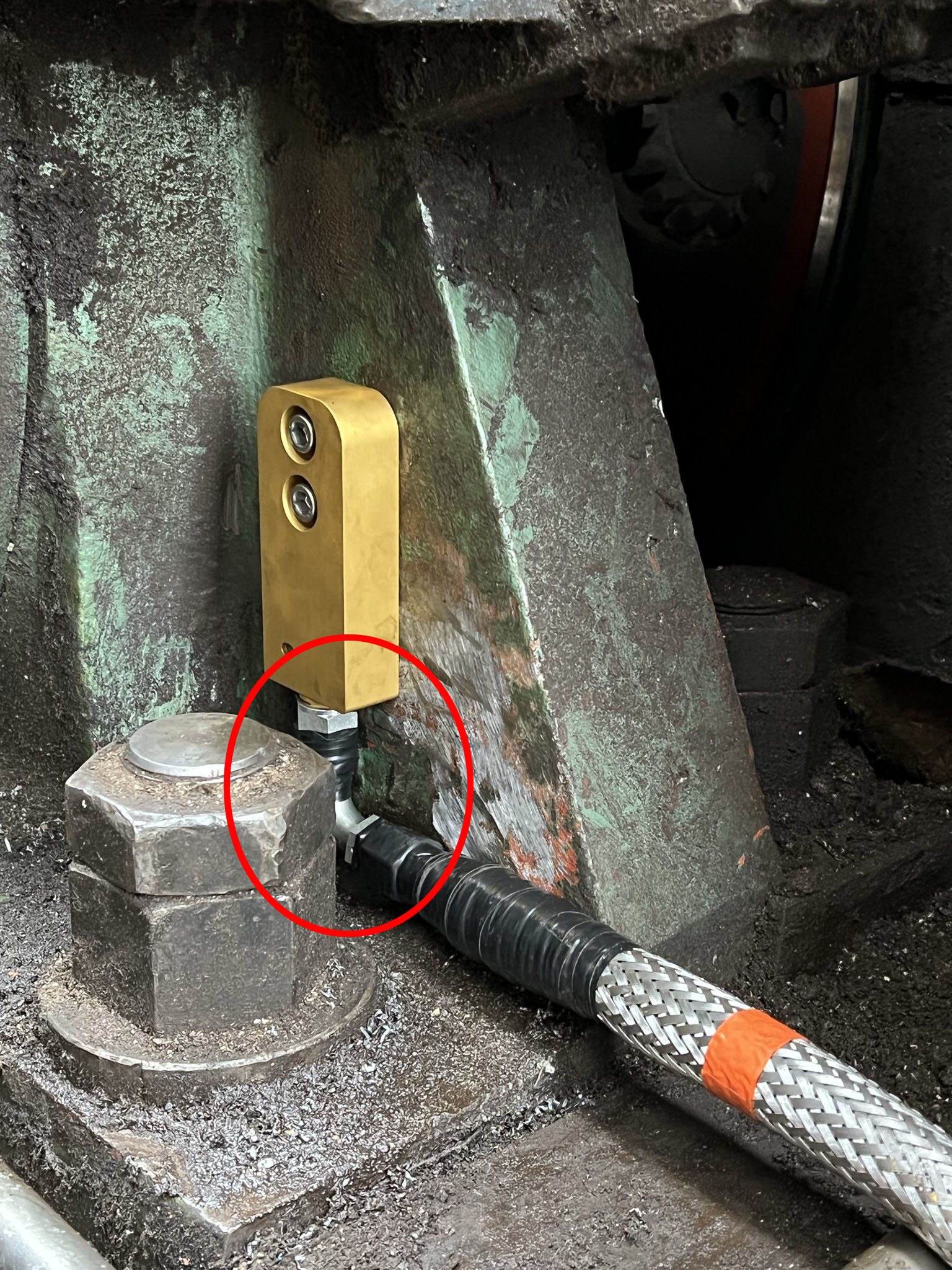
Attach the sensor using the bolts and split washers provided.
Use the level on the template to ensure that the sensor is
mounted true to perpendicular as possible. If the location of
the sensor is such that you are unable to tighten the nuts 90
degree of neck (and possibly on other neck sections should
additional necks be used), then do the following:
• Gently tighten the sensor bolts.
• Align and adjust the neck sections so that the sensor fly-lead
follows the intended path to the junction box.
• Finger tighten all nuts on the neck sections.
• Carefully remove the sensor and firmly tighten all neck
sections.
• Re-attach the sensor to the gusset and confirm that the
fly-lead follows the intended path to the junction box (ie. none
of the neck sections shift during the removal process). There
should be no stress on the neck sections
• Firmly tighten the sensor bolts. Attach the sensor using the
bolts and split washers provided. Use the level on the top of
the template to ensure that the sensor is mounted as true to
perpendicular as possible, then firmly tighten the sensor bolts.
If the location of the sensor is such that you are unable to
tighten the nuts on the 90 degree neck (and possibly on other
sections should additional necks be used), then do the
following:
• Gently tighten the sensor bolts.
• Align and adjust the neck sections so that the sensor fly-lead
follows the intended path to the junction box.
• Finger tighten all nuts on the neck sections.
• Carefully remove the sensor and firmly tighten all neck
sections.
• Re-attach the sensor to the gusset and confirm that the
fly-lead follows the intended path to the junction box (ie. none
of the neck sections shifted position during the removal
process). There should be no stress on the neck sections.
• Re-attach the sensor and firmly tighten the sensor bolts.
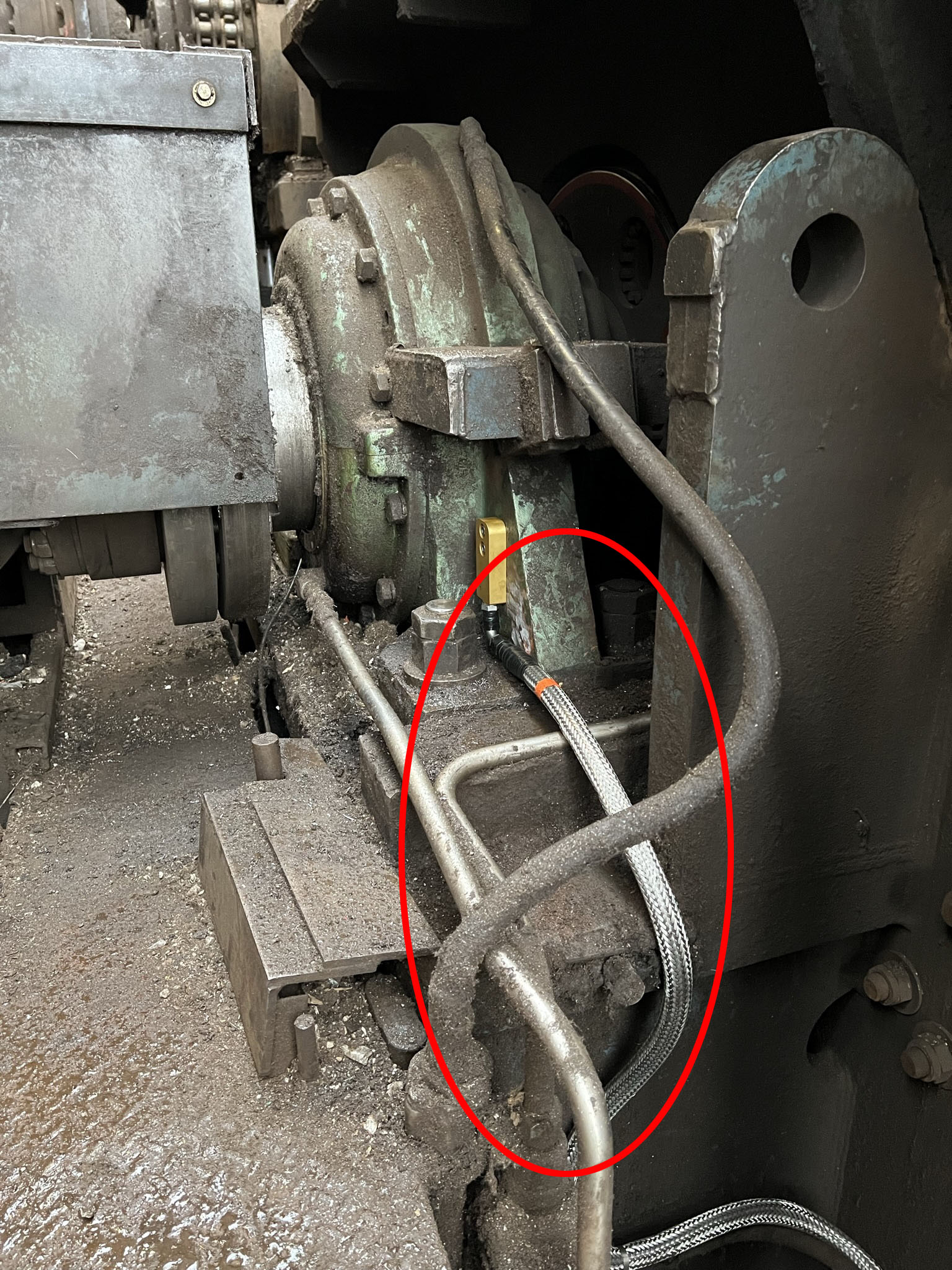
Above is an example of the sensor fly-lead following the intended path with all necks correctly aligned.
The finished mounted sensor with the template beside it